Carbide Square End Mill for Mold Steel
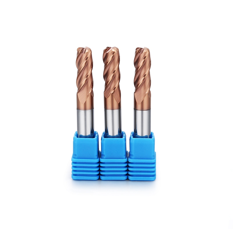
For flat floors, straight walls and shoulders. Specify the internal corner requirement, cutting length and cavity access.
Request a quote →Mold and die · Roughing to finishing
Cavity roughing, semifinishing and detailed mold surfaces.
Carbide end mills for mold steel are selected around the cavity, the machining stage and the condition of the workpiece. One mold may need a rigid cutter for bulk stock removal, a smaller tool for rest machining and a separate profile for finishing curved surfaces. KY TOOLS helps you define the cutting profile, working length and inspection requirements around the part drawing, so the tool request describes the actual operation rather than only a diameter.
Choose the cutting profile
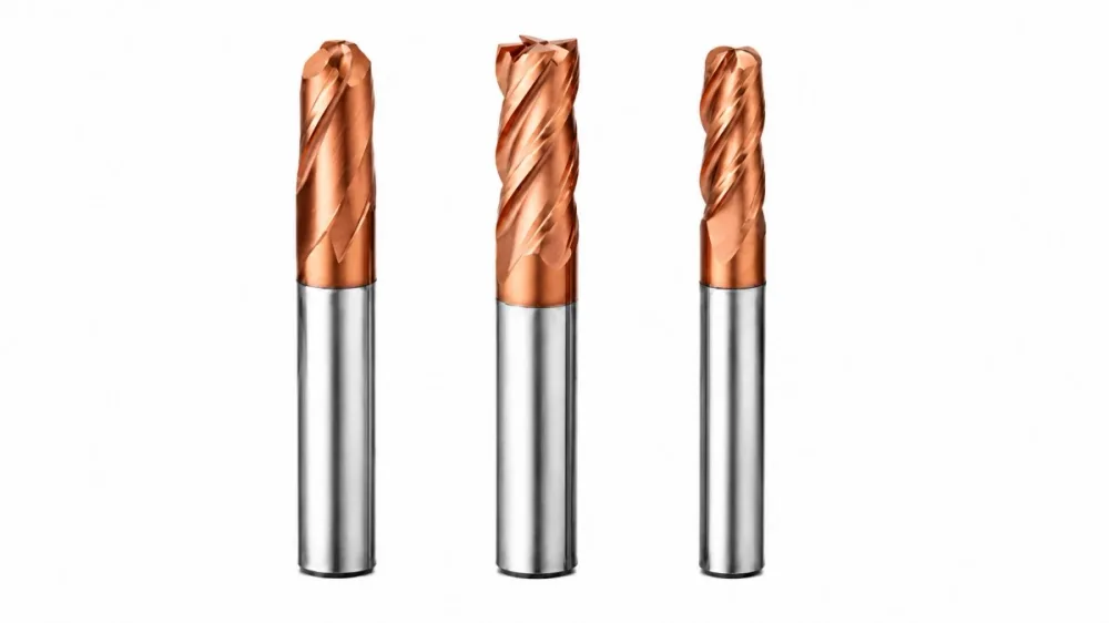
Explore the cutting profiles in this material series. Send an inquiry with your dimensions and application details.
For flat floors, straight walls and shoulders. Specify the internal corner requirement, cutting length and cavity access.
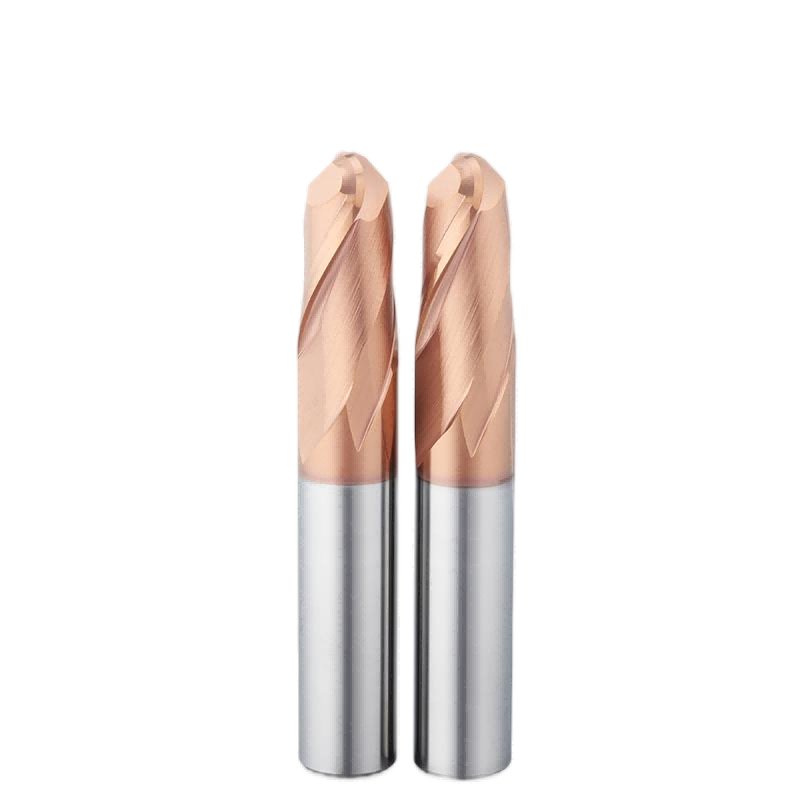
Request a quote →For curved cavities and three-dimensional mold surfaces. Specify the smallest concave radius, finishing allowance and surface requirement.
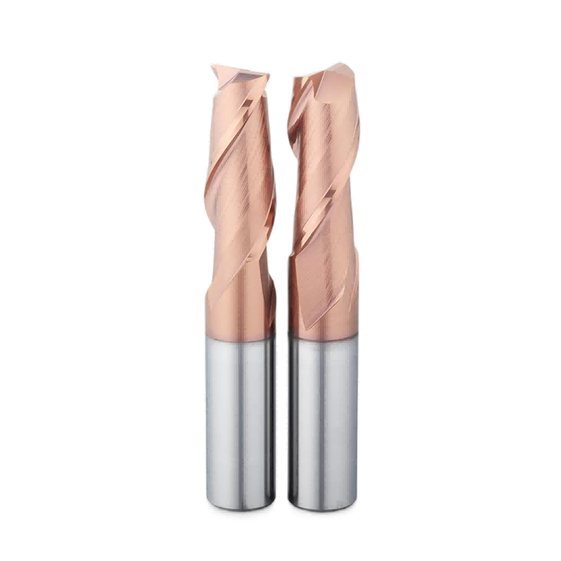
Request a quote →For pocket floors and radiused transitions. Match the corner radius to the part fillet and the remaining stock before finishing.
Request a quote →Application guide
Use the part feature and its acceptance requirements to narrow the tool choice.
Start with the cavity opening, stock condition and the path for removing chips. A larger cutter may suit open areas, while narrower pockets need a different diameter or entry strategy. Describe whether the operation includes full-width slots, open side milling or changing engagement at internal corners; these are different cutting conditions even on the same mold.
A smaller cutter removes material that the previous tool could not reach. Supply the previous cutter diameter and corner radius, together with a stock model or marked drawing. This helps identify where a cleanup tool will encounter concentrated remaining stock instead of a uniform finishing allowance.
Straight walls and flat seating surfaces require attention to the floor-to-wall transition. Decide whether the drawing requires a sharp internal boundary or permits a fillet. Include the wall height and any draft angle so the cutting length and neck clearance can be reviewed before choosing a square or corner radius end mill.
For sculpted surfaces, specify the smallest concave radius and the areas that will remain visible on the molded part. A ball nose profile can follow three-dimensional contours, but the cutter must also clear neighboring walls. Identify transitions between steep and shallow surfaces when describing the finishing operation.
Deep cavities can restrict the neck, shank and holder even when the cutting diameter fits. Provide a section through the deepest feature and the available holder dimensions. Distinguish the length needed to cut the surface from the length needed only to reach it; a long cutting edge and a relieved neck solve different problems.
Workpiece first
A steel designation is the starting point for selection. The heat-treatment state and the operation still need to be identified for the individual mold or insert.
State whether machining takes place in the supplied condition, before heat treatment or after hardening. Include the measured hardness and its scale where available. The same material name can appear on jobs with different stock conditions, and a tool chosen for roughing before treatment should not automatically be carried into final hard milling.
Use the full grade from the material certificate or drawing, including the specification or supplier designation. If you use a local equivalent, include that reference as well. For repaired inserts, identify weld repairs or areas with different material conditions so they can be considered in the application review.
For machining after hardening, compare the hardened-steel guide alongside the mold geometry. If the mold uses a stainless grade, include its corrosion-resistant material designation in the inquiry rather than assuming every mold steel has the same machining requirements.
Plan the sequence
A useful tool list explains what each cutter is expected to leave for the next operation. Record the critical surfaces as well as the nominal tool sizes.
Identify the starting stock and the regions that require bulk removal. Show enclosed pockets, interruptions and entry points in the setup information. Include the intended allowance for later operations and any areas that the roughing tool cannot reach. This makes the roughing brief useful to both tool selection and CAM programming.
Review the stock left on walls, floors and internal radii before selecting the finishing tool. Local stock concentration at a corner should be treated as a cleanup requirement. A separate semifinishing or rest-machining operation may be needed to prepare these regions; the correct sequence depends on the part and the available tools.
Mark which dimensions, profiles and surfaces will be inspected. Include the required surface finish and whether polishing or another finishing process follows milling. A mold appearance requirement, a sealing surface and a dimensional fit can require different evaluation methods, so a single general request for a smooth finish is incomplete.
Geometry and reach
Use the part geometry to decide where each profile belongs. Tool diameter, corner radius and access should be reviewed together.
Consider a square profile for flat floors, straight boundaries and shoulder features where the specified corner geometry permits it. Identify the required internal corner radius on the drawing rather than assuming the tool can create a perfectly sharp internal corner. Deep walls also require a review of the usable cutting length and holder access.
Use the ball radius and the smallest concave feature together when reviewing curved cavities. The intended toolpath and surface requirement belong in the same discussion as the cutter diameter. A smaller ball can reach smaller details, but it may also require a different operation plan for the broad surfaces around them.
A corner radius profile combines a flat end with a defined corner transition. Check that the selected radius is compatible with the part fillet and the stock left by the previous operation. Include the required radius inspection in the drawing when that feature controls the finished mold geometry.
Use the shortest practical assembly that clears the workpiece and fixture. Review the whole assembly in the cavity, including neck diameter, shank and holder. Extra overall length alone does not prove clearance, and a long flute is not a substitute for a relieved neck when access is the main constraint.
Before a production trial
When a trial needs improvement, document the operating conditions and the location of the problem before changing the tool specification.
Record where marks appear: an open wall, an inside corner, the cavity floor or a transition. Include the tool overhang, holder, workholding and relevant toolpath section. Photographs and measured results help distinguish a localized issue from a problem affecting the whole operation.
Record the point in the machining sequence where damage develops, along with the material state and stock remaining at that location. Keep the original cutting parameters and coolant or air-delivery method in the trial record. Comparing documented trials is more informative than changing several conditions at once without recording them.
Retain the approved drawing revision, tool identifier, dimensions and inspection requirements with the purchase record. For a mixed-size order, list quantities against each size and profile. If marking, packaging or sample evaluation is required, describe it in the inquiry so the quotation can address the request explicitly.
Selection & configuration
Choose geometry for the machining stage. Leave controlled finishing stock after roughing, and use ball nose or corner radius cutters to match transitions without excessive tool reach.
| Decision | What to specify | Why it matters |
|---|---|---|
| Machining stage | Roughing, rest machining or finishing | Each stage has a different balance of stock removal and profile control. |
| Cavity access | Depth, minimum opening and holder clearance | A tool diameter alone does not prove that the assembly can reach the feature. |
| Steel state | Grade and actual heat-treatment condition | Prehardened and fully hardened material should not be treated as identical. |
| Profile and radius | Flat floor, ball profile or corner radius; minimum part fillet | The cutter must fit the finished feature and the stock remaining from earlier operations. |
| Working length | Cutting length, neck dimensions, overhang and holder envelope | Cutting access and collision clearance depend on the entire assembly. |
| Surface acceptance | Critical dimensions, surface finish, inspection areas and later polishing | Finishing decisions should reflect how the mold will actually be accepted. |
| Trial conditions | Machine, holder, toolpath, cutting parameters and coolant method | A documented setup makes application feedback and repeat trials comparable. |
Swipe the table to compare all columns →
Include these details so the tool dimensions and application can be reviewed together.
From drawing to inspection
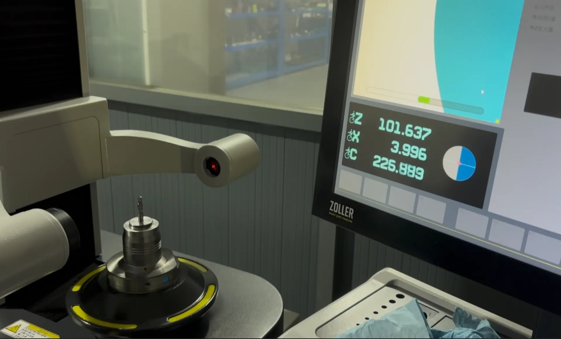
A tool specification should describe both the cutting geometry and the acceptance requirements. Mark critical dimensions on the drawing and discuss how they will be checked before ordering.
Selection questions
Practical answers for end mills for mold steel.
No. Include the actual hardness, cavity geometry and machining stage. Two parts made from the same grade can need different tools after different heat treatments.
Mold steel grade; heat-treatment condition; cavity depth; minimum internal radius; finishing allowance. Add the quantity and delivery destination. A drawing or marked part section helps identify critical dimensions and clearance constraints.
Some features may be machined with one tool, but do not assume that one diameter and reach will cover the whole cavity. Review the stock-removal regions, corner access and final surface separately. Identify the tool changes that solve a specific access or finishing requirement.
Specify the length of the surface that must be cut and the depth that must be reached. Cutting length describes the active edge; neck geometry provides access and clearance beyond it. A cavity section and holder dimensions help determine which configuration suits the feature.
A useful starting recommendation also needs the material condition, tool diameter and geometry, overhang, engagement, machine and cutting method. Include those details with the inquiry. Do not transfer values from another tool solely because its nominal diameter matches.
Send the part drawing or model, the surface acceptance requirement and the stock remaining after the previous operation. Include the cutter and holder setup, planned toolpath and machine information. After the trial, record measured results and photographs of any areas needing improvement.
List each cutting profile, diameter, corner or ball radius, cutting length, overall length and quantity separately. Mark any neck or clearance requirement on a drawing. Include identification or packaging requests, and use the agreed quotation and drawing revision as the ordering reference.
The quotation and agreed drawing define the tool configuration, inspection scope, quantity and delivery schedule. Reference images show the tool family; use the confirmed specification for ordering.
Start with your application
Send your drawing or machining requirement. Your selected tool category and a checklist will be carried into the inquiry form.