Profile & form milling
Custom Solid Carbide Form End Mills
Special contours, combined diameters and drawing-based profiles.
View tool range →Drawing-based tools · Feature consolidation
Explore drawing-based cutters for profiles, difficult access, special operations and production improvement. Start with the finished feature and its tolerance.
A custom cutter should solve a defined access, geometry or process problem. Start with the finished component and identify the dimensions that must stay related. Compare a standard special-purpose cutter with a fully custom form before combining several features into one cutting edge.
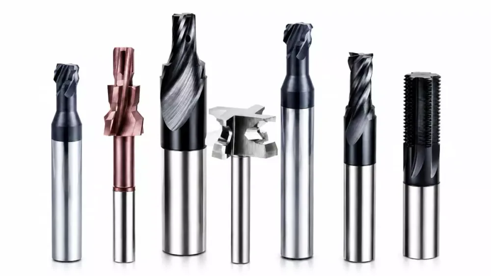
Explore the family
Compare the feature each tool solves, then open the relevant range for application and ordering details.
Profile & form milling
Special contours, combined diameters and drawing-based profiles.
View tool range →Profile & form milling
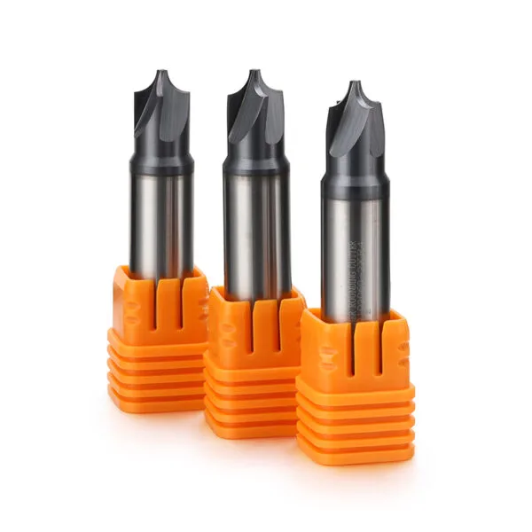
Convex edge radii and rounded external transitions.
View tool range →Complex access & contours
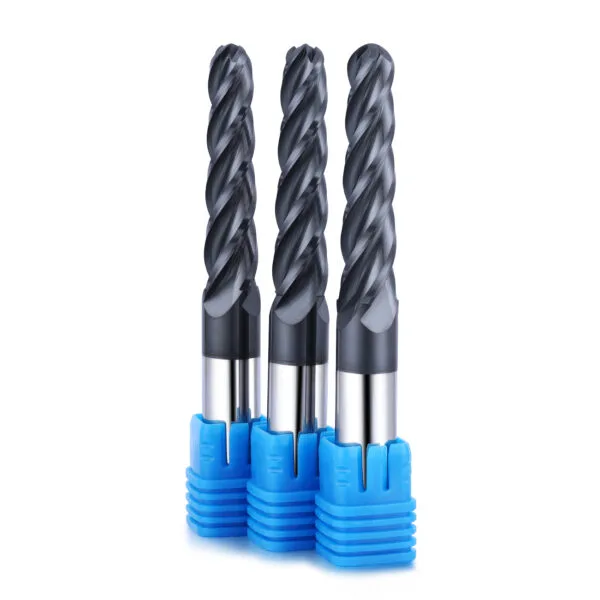
Tapered access and ball-tip contour machining.
View tool range →Complex access & contours
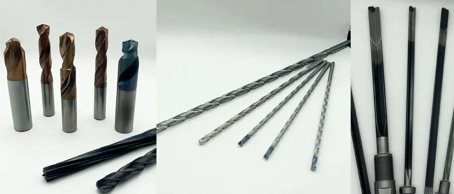
Undercuts and curved surfaces behind a restricted opening.
KY TOOLS range illustration. The exact tool geometry and coating are confirmed with your specification.
View tool range →Special operations
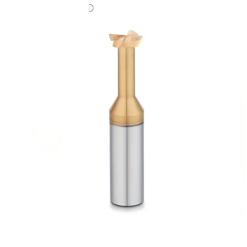
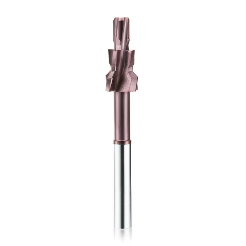
Recessed slots and grooves with a narrow entry.
View tool range →Special operations
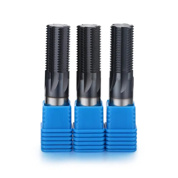
Helical interpolation of specified thread forms.
View tool range →Special operations
Edge breaking, deburring and angled features.
KY TOOLS range illustration. The exact tool geometry and coating are confirmed with your specification.
View tool range →Production optimization
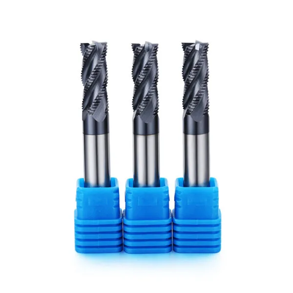
Bulk material removal before semifinishing or finishing.
View tool range →Production optimization
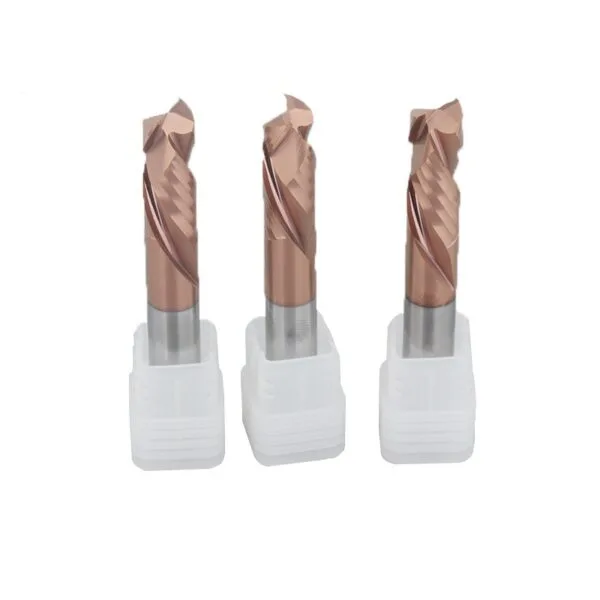
Opposed cutting directions for edge control in laminates.
View tool range →For combined non-ferrous profiles, also review PCD form milling cutters.
Application guide
Use the part feature and its acceptance requirements to narrow the tool choice.
Use one drawing to identify steps, radii and angles that need a fixed relationship.
Check that the head can enter, cut and withdraw through the available opening.
Review the load and chip space when multiple features engage together.
Application & selection
Use the drawing and actual machining conditions to define a configuration for this tool family.
Show the combined profile on a dimensioned section. Identify the datum and the tolerances between connected radii, angles and steps. A sketch of the finished contour is more useful than describing the tool only as special.
Show the entry opening, cutting position and withdrawal path. Include restrictions from nearby walls and fixtures. The head, neck and holder must all be considered when reviewing whether the profile can be reached.
State which existing operations the proposed tool would combine. Identify where several edges would engage together and how chips can leave the cut. Fewer tool changes alone does not establish that a combined form is suitable.
Mark the dimensions that need a tool report and the part features that will be evaluated in a trial. Agree on the measurement reference before ordering. Tool and part inspection can answer different questions.
Application & selection
Use the drawing and actual machining conditions to define a configuration for this tool family.
Send the part drawing, material condition and the current operation sequence. Explain whether the main issue is access, dimensional relationships, surface quality or tool changes. This keeps the proposal focused on a measurable need.
Check head diameter, neck clearance, cutting length and shank against the setup. Include the holder and fixture in restricted areas. Revisions should preserve the intended part geometry while resolving any interference.
Define the trial part, acceptance measurements and quantity. Record the agreed tool drawing revision after evaluation. A repeat order should refer to that revision and flag any subsequent change in material, setup or part design.
Selection & configuration
A custom cutter is useful when a standard geometry cannot reach the feature or when several operations can be combined. Review force, access and inspection requirements before committing to a profile.
| Decision | What to specify | Why it matters |
|---|---|---|
| Component drawing | Critical features, datums and tolerances | The finished part is the basis of the tool proposal. |
| Machine limits | Holder, spindle envelope and access | A feasible profile must also fit the actual setup. |
| Order scope | Prototype and repeat quantities | This defines the trial and production discussion. |
Swipe the table to compare all columns →
Include these details so the tool dimensions and application can be reviewed together.
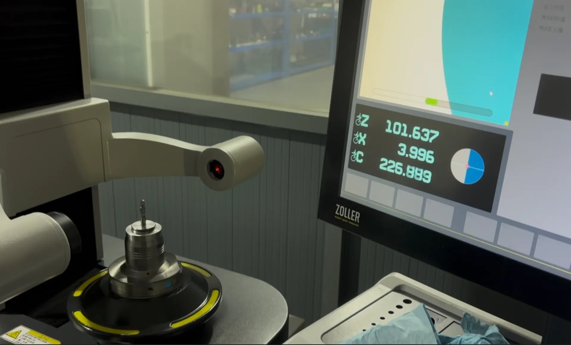
From drawing to inspection
A tool specification should describe both the cutting geometry and the acceptance requirements. Mark critical dimensions on the drawing and discuss how they will be checked before ordering.
Selection questions
Practical answers for custom cutting tools.
Send the component drawing, material and present machining sequence. Mark the critical features and describe the issue with the current process so a tool concept can be reviewed.
Component drawing; critical dimensions; material; current process; machine constraints; expected batch quantity. Add the quantity and delivery destination. A drawing or marked part section helps identify critical dimensions and clearance constraints.
The quotation and agreed drawing define the tool configuration, inspection scope, quantity and delivery schedule. Reference images show the tool family; use the confirmed specification for ordering.
Start with your application
Send your drawing or machining requirement. Your selected tool category and a checklist will be carried into the inquiry form.