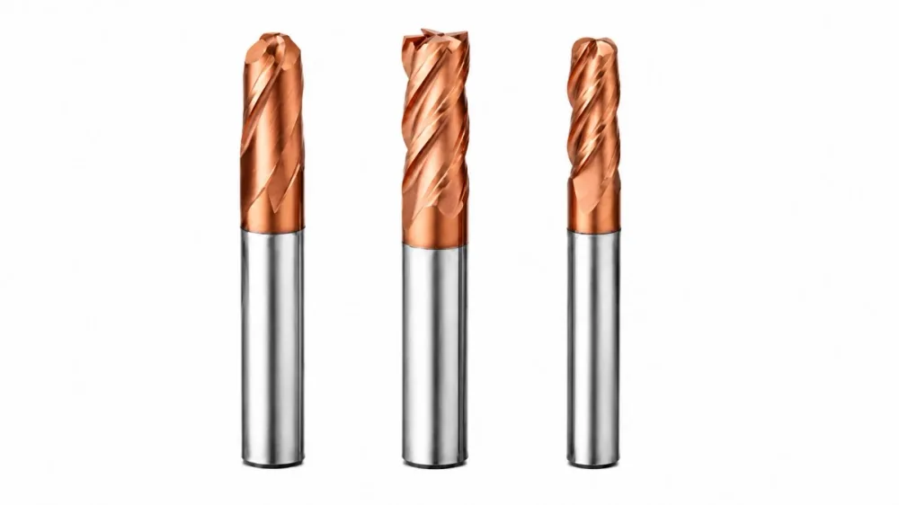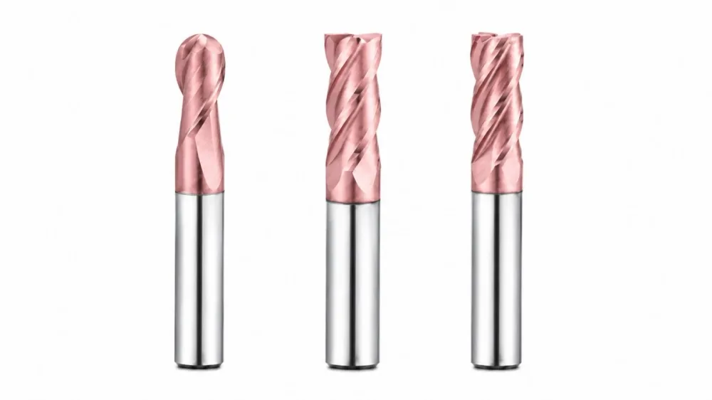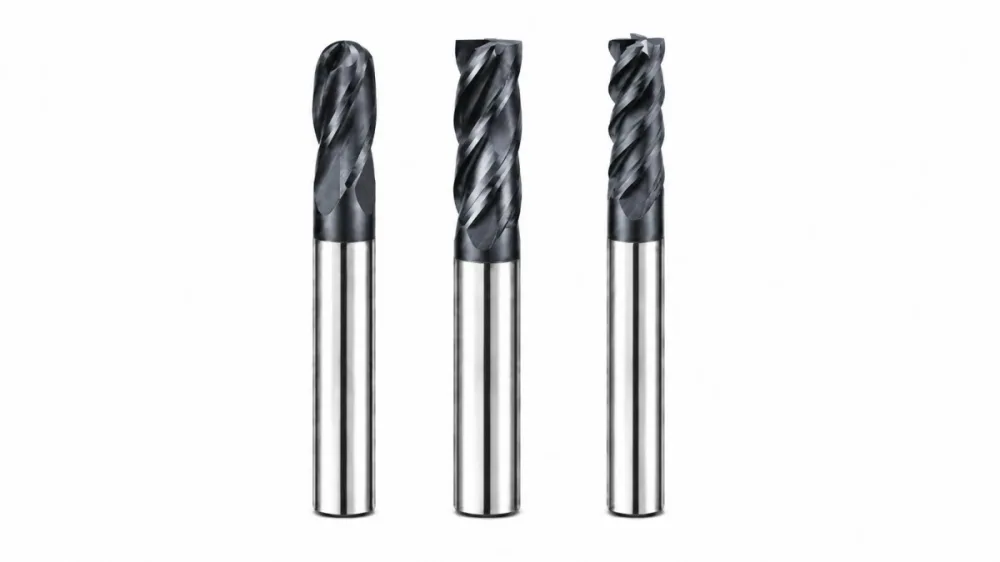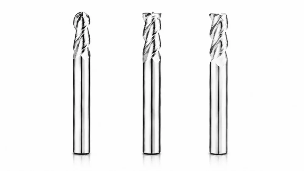
By workpiece material
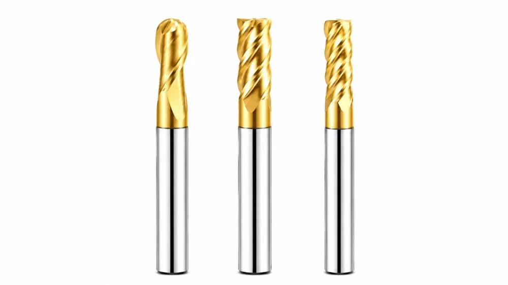
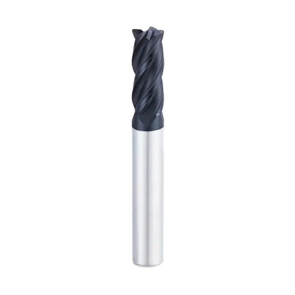
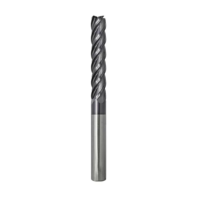
End Mills for Carbon Steel
Slotting, shoulders and general-purpose steel milling.
View tool range →Milling tools · Material, profile and reach
Choose a milling cutter by workpiece material, cutting profile and required reach. Compare material-specific ranges with square, ball nose and corner radius geometries.
Choose a carbide end mill in three decisions: the workpiece condition, the machined feature and the distance needed to reach it. Use the material ranges for application context, then compare square, ball nose and corner radius profiles. Keep cutting length separate from overall reach.
Explore the family
Compare the feature each tool solves, then open the relevant range for application and ordering details.
By workpiece material
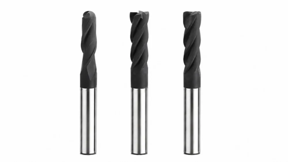
Slotting, shoulders and general-purpose steel milling.
View tool range →By workpiece material
Cavity roughing, semifinishing and detailed mold surfaces.
View tool range →By workpiece material
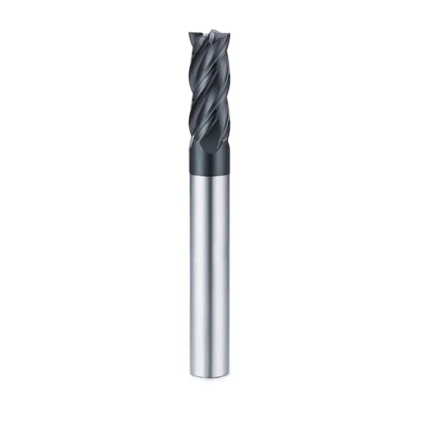
Controlled semifinishing and finishing of heat-treated components.
View tool range →By workpiece material
Pocketing, profiling and shoulder milling in stainless alloys.
View tool range →By workpiece material
Sharp-edge cutters for pockets, slots and non-ferrous profiles.
View tool range →By workpiece material
Material-specific tools for titanium pockets, profiles and contours.
View tool range →By workpiece material
Diamond-coated tools for electrodes, molds and abrasive graphite milling.
View tool range →By profile and reach
Flat-bottom pockets, slots and square shoulders.
View tool range →By profile and reach
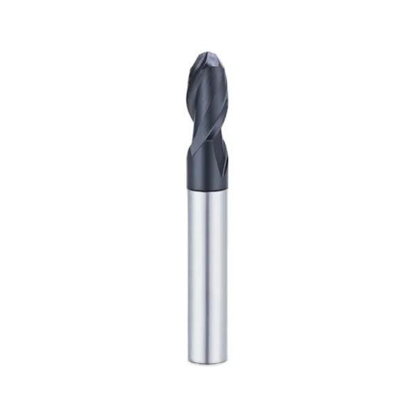
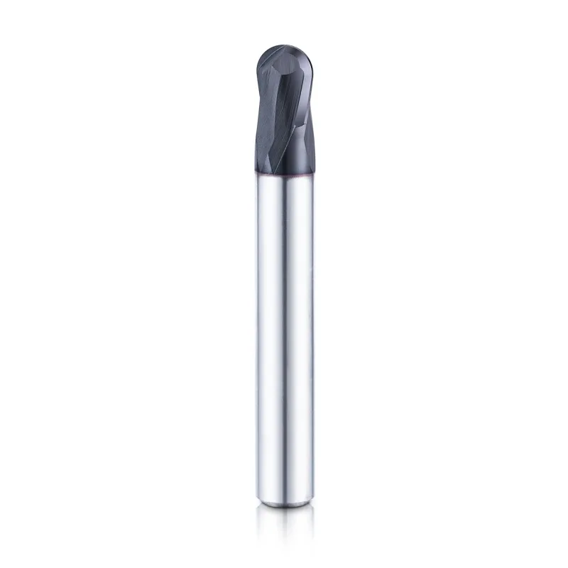
Three-dimensional contours and curved finishing surfaces.
View tool range →By profile and reach
Flat-bottom milling with a reinforced corner radius.
View tool range →By profile and reach
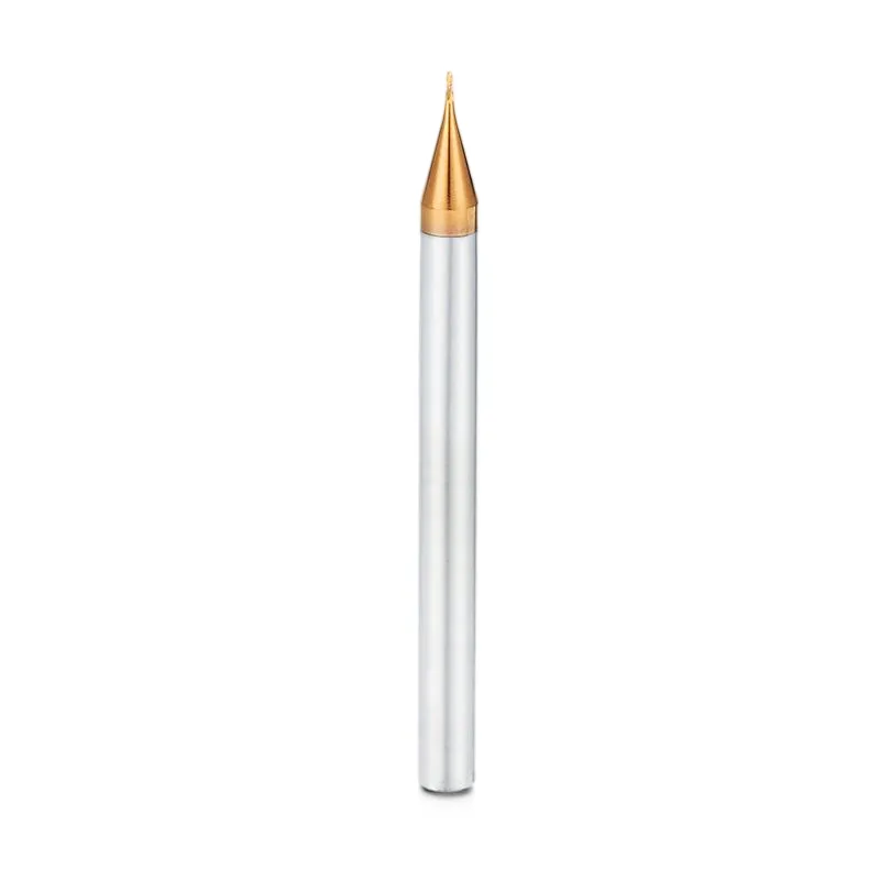
Small features, narrow slots and miniature mold details.
View tool range →By profile and reach
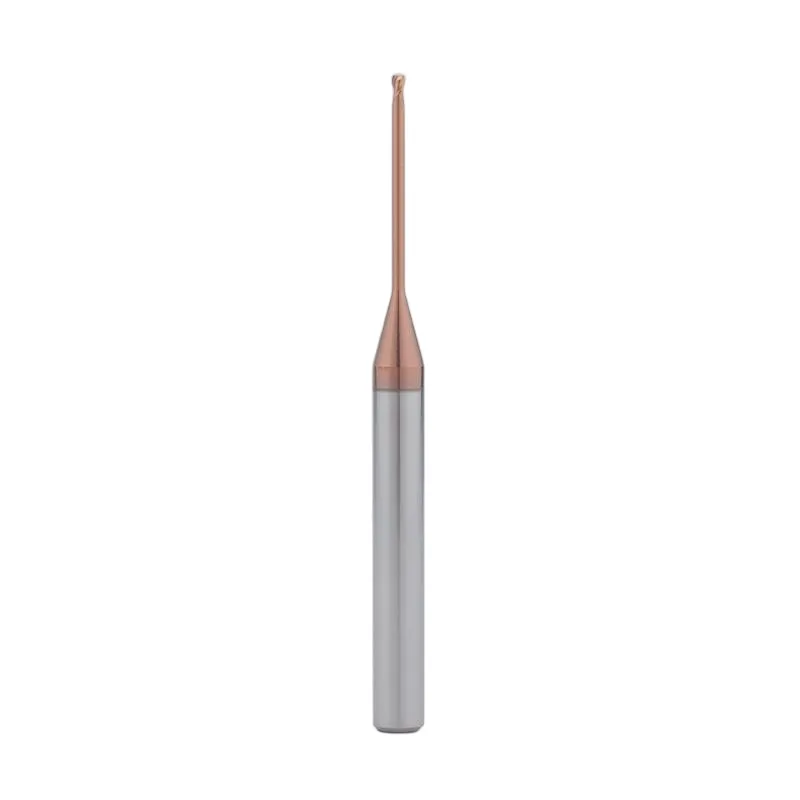
Deep cavities with neck clearance behind a short cutting edge.
View tool range →By profile and reach
Extended access to recessed features and obstructed surfaces.
View tool range →By profile and reach
Extended cutting edges for deeper side-wall engagement.
View tool range →Application guide
Use the part feature and its acceptance requirements to narrow the tool choice.
Begin with the exact workpiece grade and condition, then review geometry and coating.
Match a flat floor, curved surface or fillet to the corresponding cutter shape.
Check the complete tool and holder envelope for deep or obstructed features.
Application & selection
Use the drawing and actual machining conditions to define a configuration for this tool family.
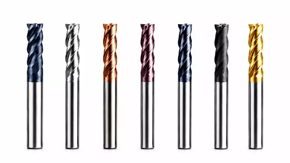
Start with the exact workpiece grade and its current condition. Use the steel, stainless, aluminum or other material page to describe the operation, then select a profile. A category photograph or a coating color does not establish a hardness rating or cutting recommendation.
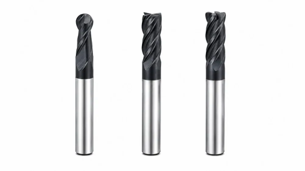
Square, ball nose and corner radius tools serve different finished geometries. Mark flat floors, concave contours and permitted fillets on the part drawing. Use the smallest relevant feature to review the profile without forcing one cutter to machine every region.
Keep cutting length, neck length and overall length separate. Show the deepest feature and the holder envelope in a section view. Choose the shortest practical assembly that reaches the surface while clearing the workpiece and fixture.
Application & selection
Use the drawing and actual machining conditions to define a configuration for this tool family.
Record the stock-removal region and the finish requirements before listing tool sizes. Identify corners that need rest machining and surfaces requiring a different profile. This ties every cutter in the list to a specific task.
Narrow ribs, deep pockets and long walls may need micro-diameter, long-neck or long-flute options. Describe the access problem before choosing a longer tool. Extra reach and extra cutting length are not interchangeable.
List profile, diameter, radius, cutting length and quantity for each tool. Include the workpiece condition and machine setup once for the shared operation, then mark exceptions against the affected tool. Retain the approved dimensions for repeat purchases.
Selection & configuration
Match the cutting edge and coating to the material first, then choose the shortest reach that clears the part. Long flute length and long reach solve different machining problems.
| Decision | What to specify | Why it matters |
|---|---|---|
| Material | Grade, hardness and treatment | These guide the cutting material and edge preparation review. |
| Feature | Floor, wall, curve or undercut | A profile suitable for one surface may leave stock on another. |
| Reach | Cutting length, neck and holder clearance | The shortest workable assembly is usually the starting point. |
Swipe the table to compare all columns →
Include these details so the tool dimensions and application can be reviewed together.

From drawing to inspection
A tool specification should describe both the cutting geometry and the acceptance requirements. Mark critical dimensions on the drawing and discuss how they will be checked before ordering.
Selection questions
Practical answers for carbide end mills.
Use both. The feature determines the shape that can produce it, while the workpiece condition affects the cutting geometry and coating. Start with the constraint that rules out the most options for your part.
Material grade and hardness; operation; diameter; flute length; reach; holder and machine details. Add the quantity and delivery destination. A drawing or marked part section helps identify critical dimensions and clearance constraints.
The quotation and agreed drawing define the tool configuration, inspection scope, quantity and delivery schedule. Reference images show the tool family; use the confirmed specification for ordering.
Start with your application
Send your drawing or machining requirement. Your selected tool category and a checklist will be carried into the inquiry form.