Carbide Square End Mill For Aluminum
For aluminum pockets, flat floors and shoulders. Include alloy, stock form and the path available for chip removal.
Request a quote →Aluminum alloys · Chip space and edge quality
Sharp-edge cutters for pockets, slots and non-ferrous profiles.
Aluminum applications range from open profiles to deep pockets and thin housings. Alloy condition, chip volume and the finish requirement influence tool selection. Match the edge geometry and flute space to the operation before considering a coating or a higher flute count.
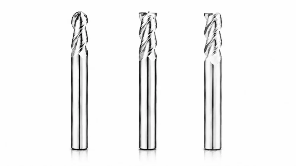
Choose the cutting profile
Choose a profile for the feature you need to machine, then request dimensions and application support for this aluminum series.
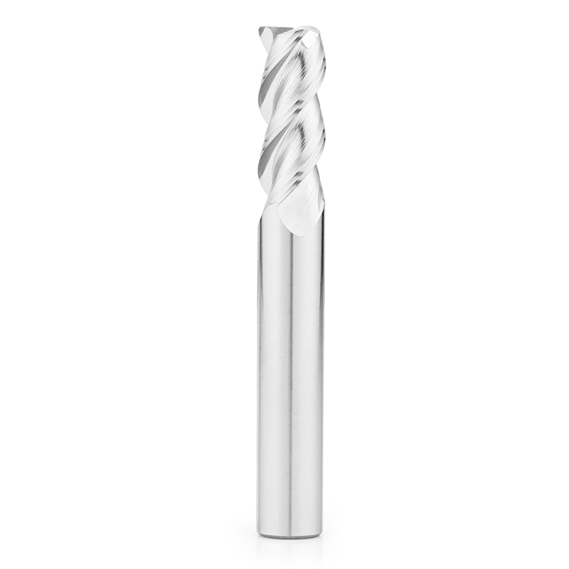
For aluminum pockets, flat floors and shoulders. Include alloy, stock form and the path available for chip removal.
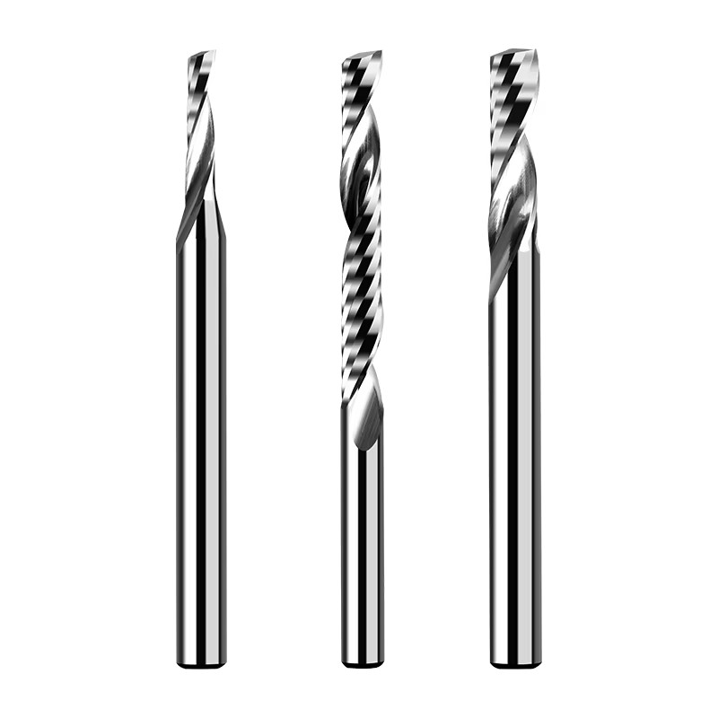
Request a quote →For operations requiring review of a single-flute configuration. Specify machine capability, engagement and the intended chip-removal method.
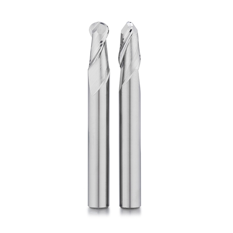
Request a quote →For curved aluminum parts and sculpted surfaces. Identify the minimum internal radius and appearance requirements.
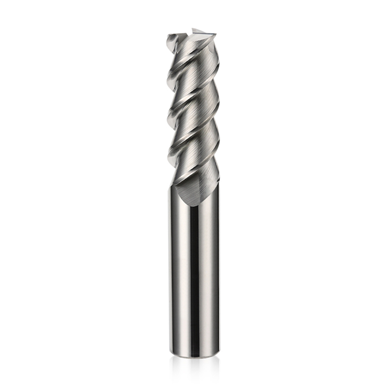
Request a quote →For aluminum pockets and blended shoulders. Specify the corner radius and the wall or floor thickness around the cut.
Request a quote →Application guide
Use the part feature and its acceptance requirements to narrow the tool choice.
Allow chips to escape through the working depth and verify holder clearance above the walls.
Review wall support and the order of roughing and finishing passes.
Include the finish acceptance method and whether the surface will be anodized or otherwise treated.
Application & selection
Tool selection for aluminum should reflect the workpiece and machining operation rather than color or coating appearance.
Specify the alloy designation and whether the component is machined from wrought stock, a casting or another form. Include the supplied condition and any known composition information relevant to the job. Different stock forms should not be treated as identical applications.
Identify deep pockets, thin walls and narrow floor regions. Include the fixture and the sequence in which supporting material is removed. A cutter that fits the opening still needs sufficient clearance for the shank and holder.
Mark sealing, mating and visible surfaces separately. Include the intended inspection method and any subsequent coating or finishing operation. A request for a bright surface does not replace a dimensional or roughness requirement.
Application & selection
Use the geometry of the feature and the machine setup to narrow the options.
Use the flat floor, shoulder and corner requirements to define the cutting profile. Include entry strategy and pocket depth. Specify whether the tool must remove bulk stock or finish a previously machined surface.
When requesting a single-flute tool, include machine speed capability, feed settings, engagement and chip-removal method. Do not assume the flute count alone establishes suitable cutting data or a better result for every aluminum operation.
Choose the ball radius around the smallest concave region while checking neighboring surfaces for clearance. Identify the finish areas and remaining stock. Broad surfaces and small details may need separate operations.
Match the cutter corner to the permitted part fillet. Include wall thickness and transitions where the remaining stock changes. The corner radius should be an explicit drawing dimension when it controls the finished feature.
Application & selection
A clear sequence makes it easier to compare tools without losing the context of the setup.
Record how the tool enters the stock and how chips leave enclosed areas. Include coolant or air delivery and any fixture restrictions. Show features where the path changes abruptly or access becomes narrow.
Identify stock left in corners, floors and thin-wall regions before finishing. Note any distortion or edge condition that already exists. The finishing tool should be reviewed against this intermediate state.
Measure the specified surfaces and retain photographs of visible features and tool edges. Keep the setup and parameters with the accepted drawing revision so future orders can reference the evaluated configuration.
Selection & configuration
Large chip space and an appropriate edge finish help limit built-up edge. Consider alloy silicon content, thin walls and holder runout before selecting flute count or a surface treatment.
| Decision | What to specify | Why it matters |
|---|---|---|
| Alloy and temper | Exact designation and casting or wrought condition | The broad label aluminum hides important material differences. |
| Chip clearance | Pocket depth, slot width and evacuation method | Packed chips can damage the surface and cutting edge. |
| Surface requirement | Finish, burr limits and subsequent treatment | A cosmetically important face may need its own finishing operation. |
Swipe the table to compare all columns →
Include these details so the tool dimensions and application can be reviewed together.

From drawing to inspection
A tool specification should describe both the cutting geometry and the acceptance requirements. Mark critical dimensions on the drawing and discuss how they will be checked before ordering.
Selection questions
Practical answers for end mills for aluminum.
Consider the alloy, abrasiveness, profile and production volume. Share the present wear pattern and quality requirements so PCD can be evaluated against a carbide solution for that operation.
Alloy and temper; silicon content if known; wall thickness; surface finish; spindle speed range. Add the quantity and delivery destination. A drawing or marked part section helps identify critical dimensions and clearance constraints.
The quotation and agreed drawing define the tool configuration, inspection scope, quantity and delivery schedule. Reference images show the tool family; use the confirmed specification for ordering.
Start with your application
Send your drawing or machining requirement. Your selected tool category and a checklist will be carried into the inquiry form.