Carbide Square End Mill For Carbon Steel
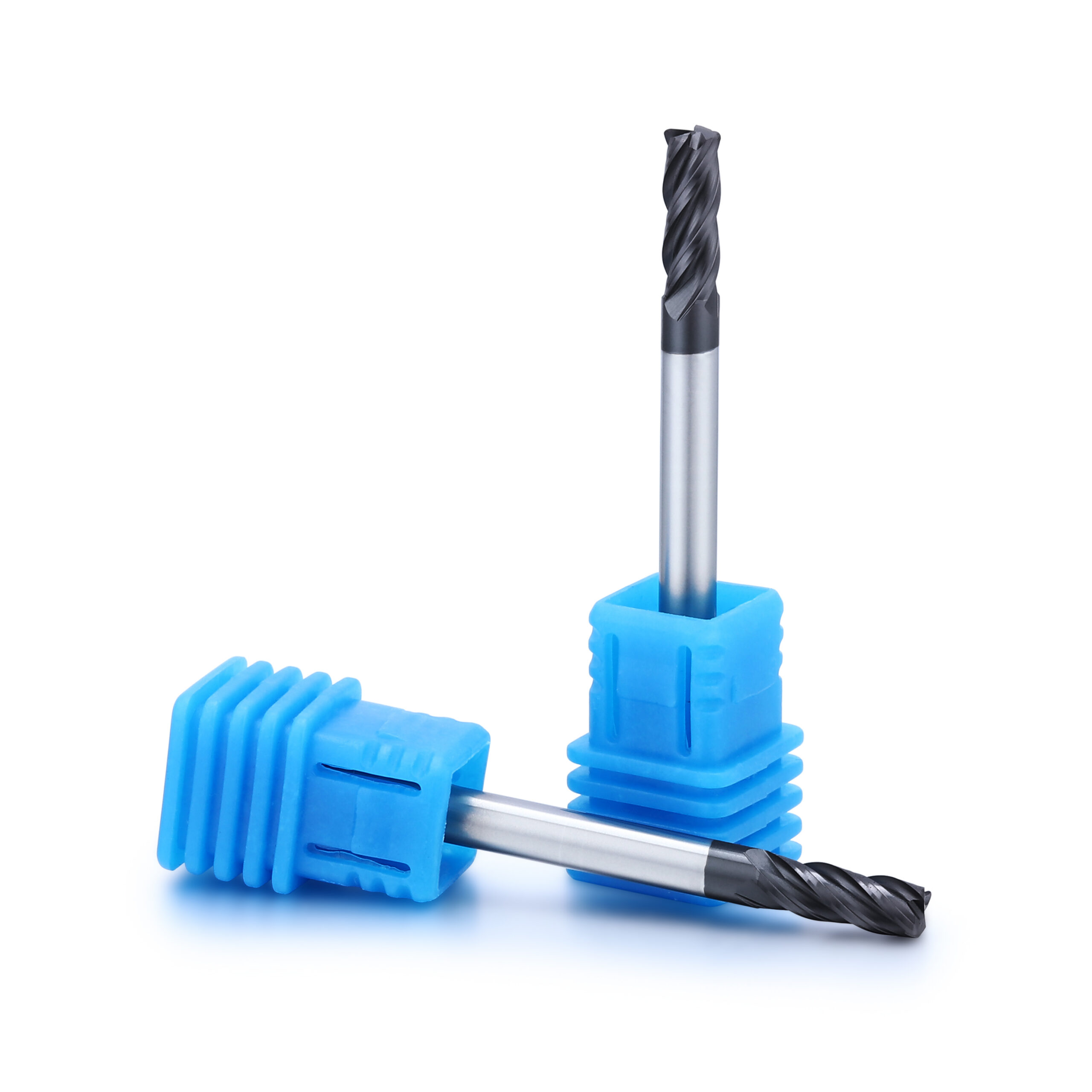
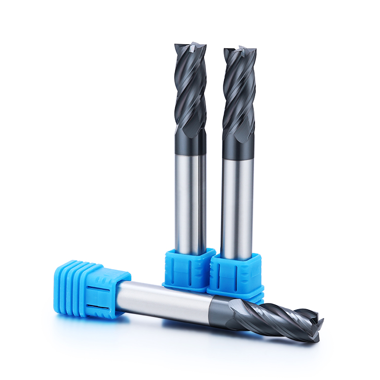
For slots, shoulders and flat floors in carbon-steel parts. Describe the entry condition and whether the cut is full width or peripheral.
Request a quote →Carbon steel · Slots, pockets and shoulders
Slotting, shoulders and general-purpose steel milling.
Carbon steel milling covers both open-sided cuts and enclosed features with very different chip space. Start with the steel condition and the amount of radial engagement. A tool that works well along an open wall may need a different cutting strategy when its full diameter enters a slot.
Choose the cutting profile
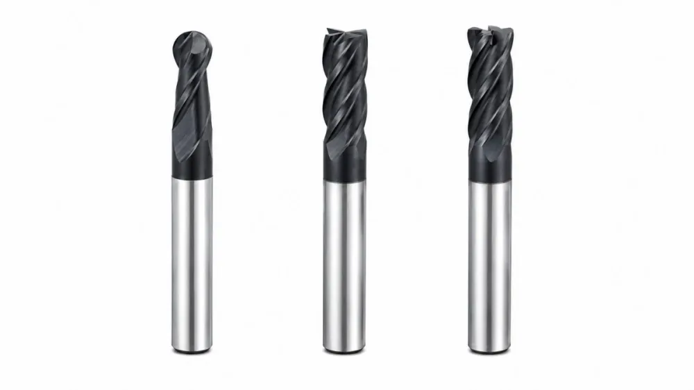
Choose a profile for the feature you need to machine, then request dimensions and application support for this carbon steel series.
For slots, shoulders and flat floors in carbon-steel parts. Describe the entry condition and whether the cut is full width or peripheral.
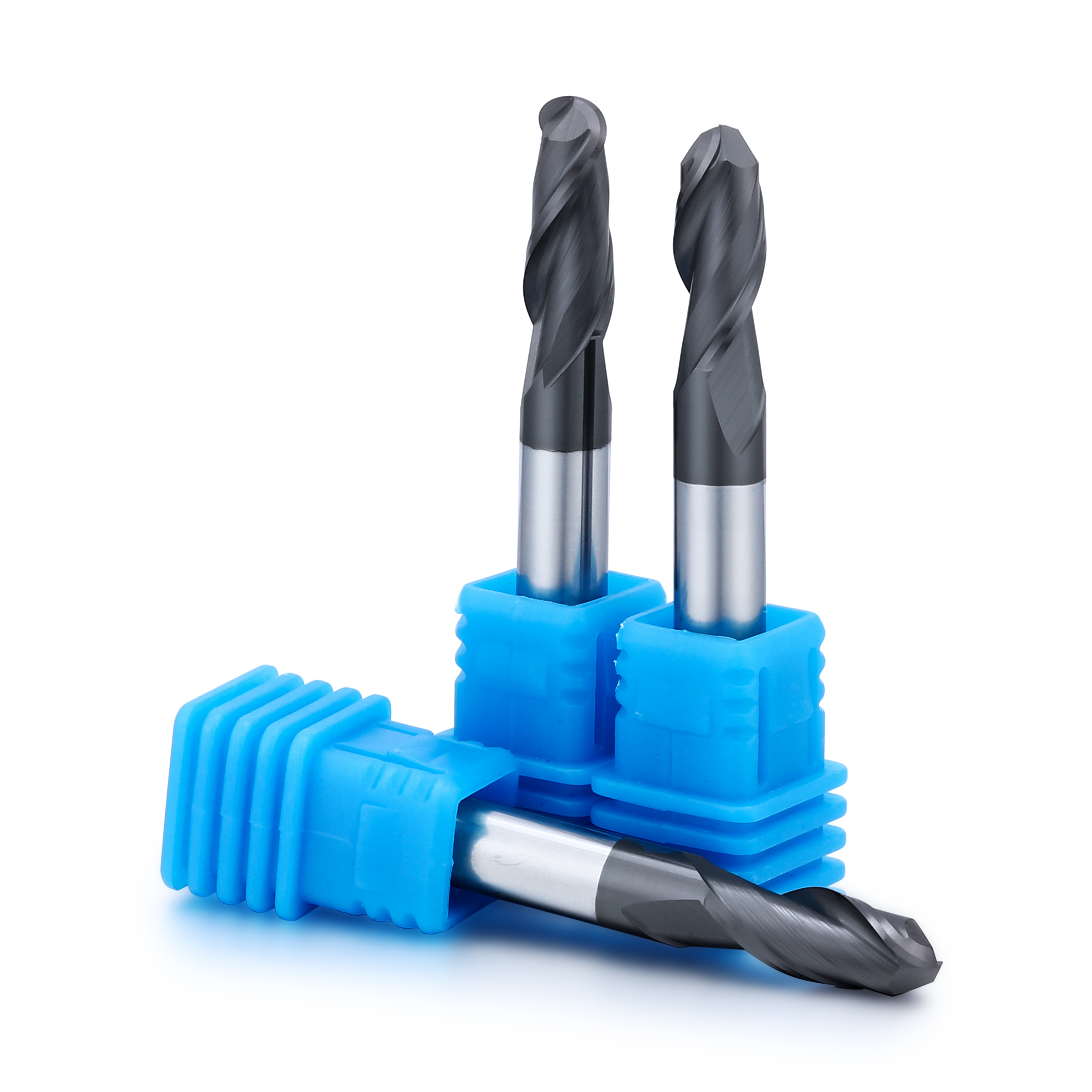
Request a quote →For curved carbon-steel profiles. Match the ball radius to the concave feature and include the required finish.
Request a quote →For pockets and radiused shoulders. Specify the corner radius, wall height and stock-removal stage.
Request a quote →Application guide
Use the part feature and its acceptance requirements to narrow the tool choice.
Account for the full cutter width in engagement and provide space for chips to leave the feature.
Select the profile around wall straightness, floor finish and whether a corner fillet is permitted.
Plan roughing and finishing separately when wall accuracy or corner detail matters.
Application & selection
The surface condition and the feature being cut help define a useful carbon-steel milling request.
Provide the full material designation and whether the part is supplied as bar, plate, forging or another stock form. Include hardness or heat-treatment information when available. Do not substitute a general steel label for a known drawing specification.
Identify scale, existing holes, welds and interrupted boundaries along the cut. Show where the cutter first enters the stock. These details help distinguish a continuous side-milling operation from a variable-engagement roughing job.
Thin sections and long walls should be identified on the drawing together with the clamping locations. Include the intended sequence if support changes as material is removed. Tool choice and workholding should be considered together.
Application & selection
Similar diameters can serve very different features and machining stages.
State whether the tool will cut at full width, enter a prepared opening or follow a pocketing path. Include pocket depth and the available chip-removal method. A tool intended for side milling should not be assumed suitable for every entry strategy.
Specify wall height, floor geometry and the permitted corner radius. Note which surfaces control fit and which are noncritical. This distinguishes the required cutting length from any extra reach needed to clear the fixture.
For contoured parts, include the smallest internal radius and any surfaces requiring a separate finish pass. Use the ball or corner radius profile that fits the drawing, with access checked at the most restricted position.
For repeat orders, retain the approved tool dimensions, drawing revision and setup record. If edge life changes between batches, record the stock condition and cutting parameters before requesting a geometry change.
Application & selection
A short, complete application brief reduces ambiguous size-only quotations.
Send a drawing with the slot, wall or profile highlighted. Add the material grade and critical dimensions. A section view is useful wherever the holder or tool neck approaches the component.
Specify diameter, cutting length, overall length and any corner radius. Include shank requirements and quantity for each size. Identify custom dimensions separately from the standard tools already used in the process.
State the dimensional and surface requirements and the operation to be evaluated. Keep photographs and measurements with the trial setup. A documented result gives the next tool review a concrete starting point.
Selection & configuration
For full-width slots, prioritize chip space and stable engagement. Side milling allows a different flute count and radial engagement; account for the steel grade and its condition.
| Decision | What to specify | Why it matters |
|---|---|---|
| Steel condition | Exact grade and supplied or heat-treated condition | Machinability varies even within the same broad material family. |
| Engagement | Slotting or side milling and intended depth | The same cutter sees different loads in open and enclosed cuts. |
| Corner requirement | Sharp shoulder or specified fillet | A corner radius tool leaves a different transition from a square cutter. |
Swipe the table to compare all columns →
Include these details so the tool dimensions and application can be reviewed together.
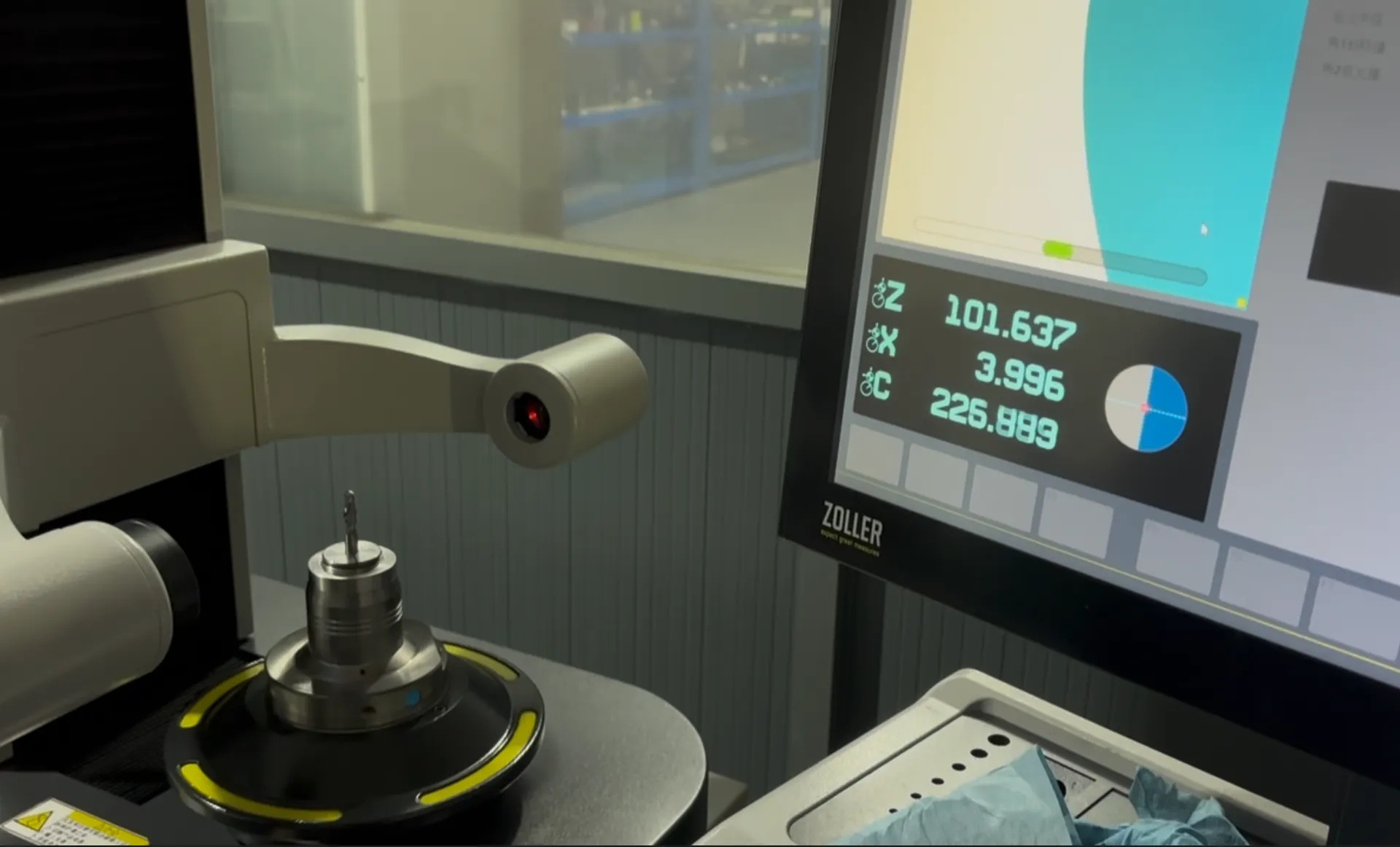
From drawing to inspection
A tool specification should describe both the cutting geometry and the acceptance requirements. Mark critical dimensions on the drawing and discuss how they will be checked before ordering.
Selection questions
Practical answers for end mills for carbon steel.
It may, but the flute space and operating conditions must suit both operations. Share the slot depth and the side-milling engagement so the tool and process can be evaluated together.
Steel grade; hardness; slot width or radial engagement; roughing versus finishing. Add the quantity and delivery destination. A drawing or marked part section helps identify critical dimensions and clearance constraints.
The quotation and agreed drawing define the tool configuration, inspection scope, quantity and delivery schedule. Reference images show the tool family; use the confirmed specification for ordering.
Start with your application
Send your drawing or machining requirement. Your selected tool category and a checklist will be carried into the inquiry form.