Micro slots
Check the opening width and whether chips can leave a narrow, enclosed feature.
Miniature features · Runout and working length
Small features, narrow slots and miniature mold details.
Micro milling is governed by the smallest feature and the tool assembly as much as by nominal diameter. Describe the narrowest slot, smallest radius and required reach. The holder, runout and chip removal method are essential inputs when reviewing a miniature cutter.
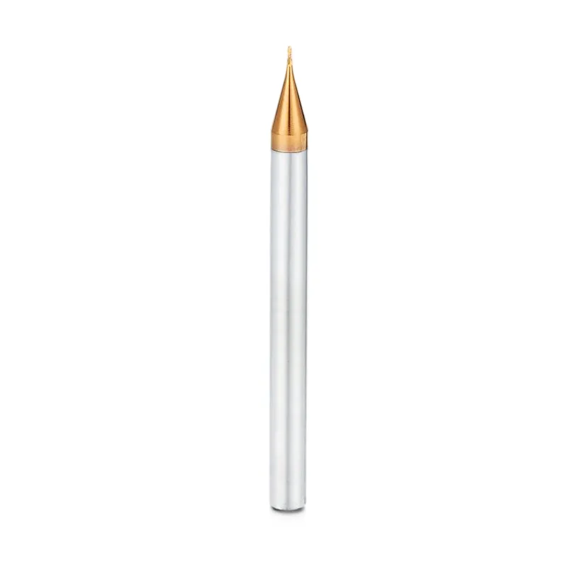
Application guide
Use the part feature and its acceptance requirements to narrow the tool choice.
Check the opening width and whether chips can leave a narrow, enclosed feature.
Use the internal radius and depth to define profile and reach together.
Separate fine finishing from bulk stock removal to keep the feature requirements clear.
Selection & configuration
At small diameters, runout and edge condition are critical. Use the shortest working length and evaluate chip evacuation before increasing depth.
| Decision | What to specify | Why it matters |
|---|---|---|
| Minimum feature | Slot width, smallest inside radius and depth | The feature determines both cutting diameter and access. |
| Tool assembly | Holder, measured runout and stick-out | Small cutters are sensitive to assembly variation. |
| Working length | Required cutting length and relieved reach | Unneeded length reduces support behind the edge. |
Swipe the table to compare all columns →
Include these details so the tool dimensions and application can be reviewed together.
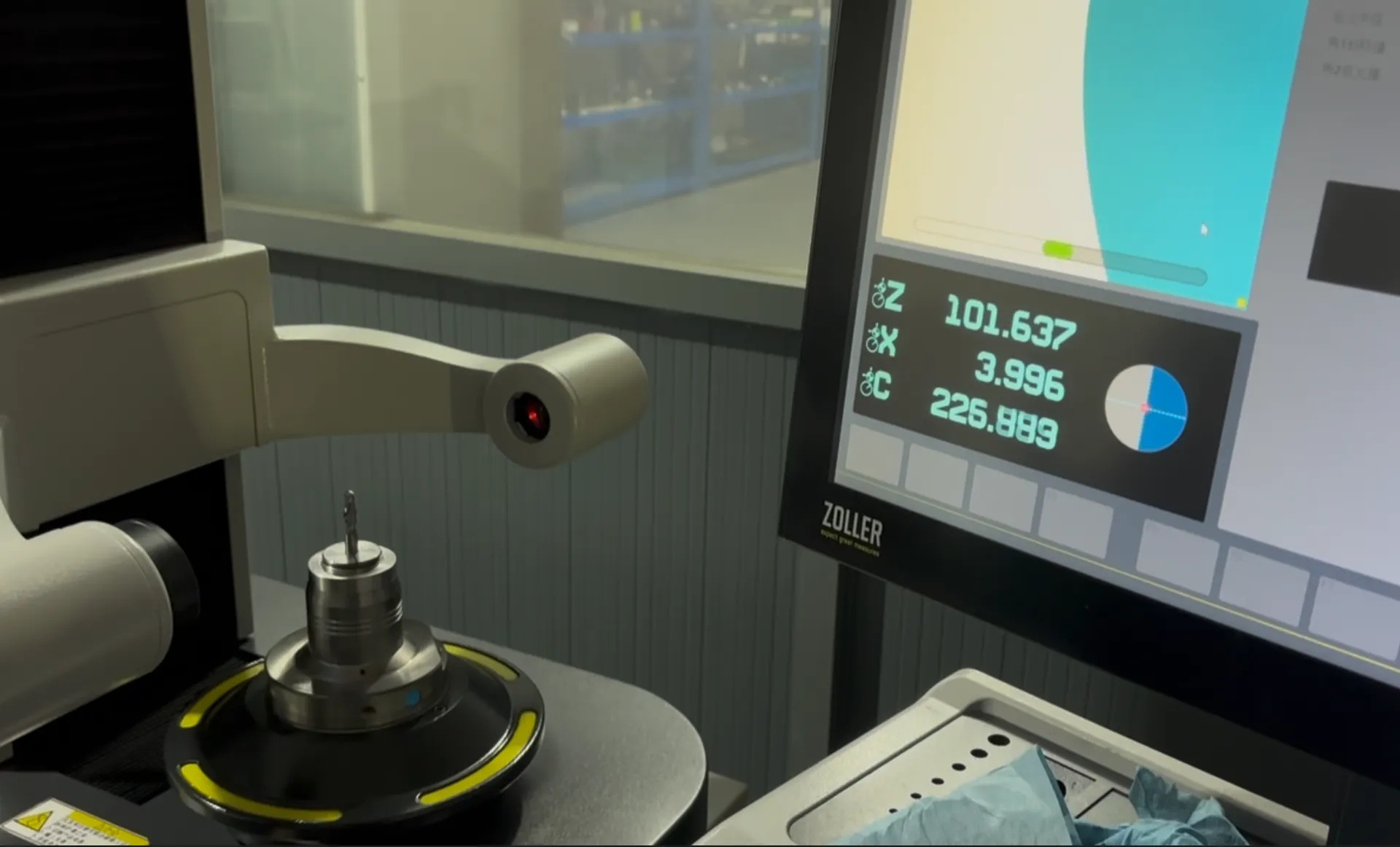
From drawing to inspection
A tool specification should describe both the cutting geometry and the acceptance requirements. Mark critical dimensions on the drawing and discuss how they will be checked before ordering.
Selection questions
Practical answers for micro diameter end mills.
Use the diameter needed for the feature, not the smallest available tool. Extra-small diameters may increase sensitivity to runout and deflection without improving a feature that a larger tool can reach.
Cutting diameter; flute length; overall reach; shank; corner radius; part drawing. Add the quantity and delivery destination. A drawing or marked part section helps identify critical dimensions and clearance constraints.
The quotation and agreed drawing define the tool configuration, inspection scope, quantity and delivery schedule. Reference images show the tool family; use the confirmed specification for ordering.
Start with your application
Send your drawing or machining requirement. Your selected tool category and a checklist will be carried into the inquiry form.