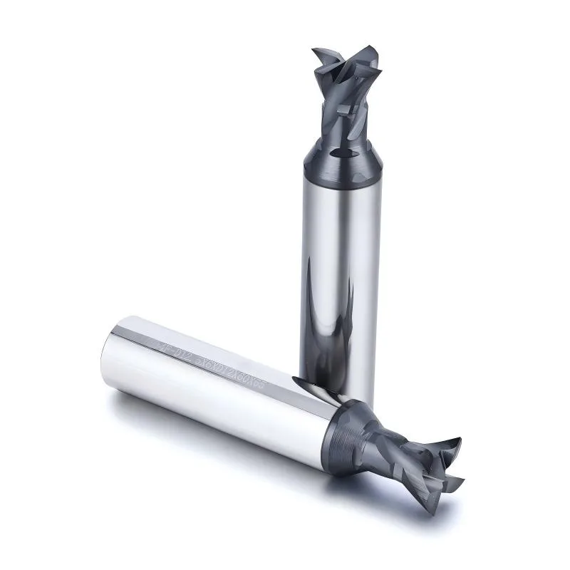
PCD Dovetail End Mills
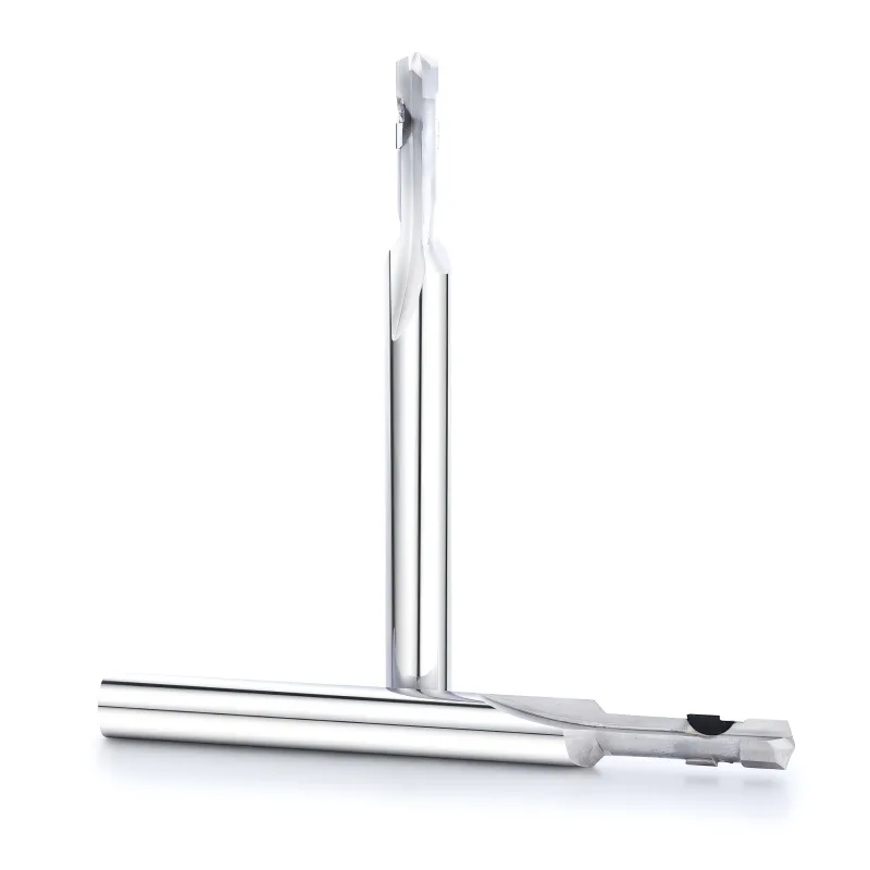
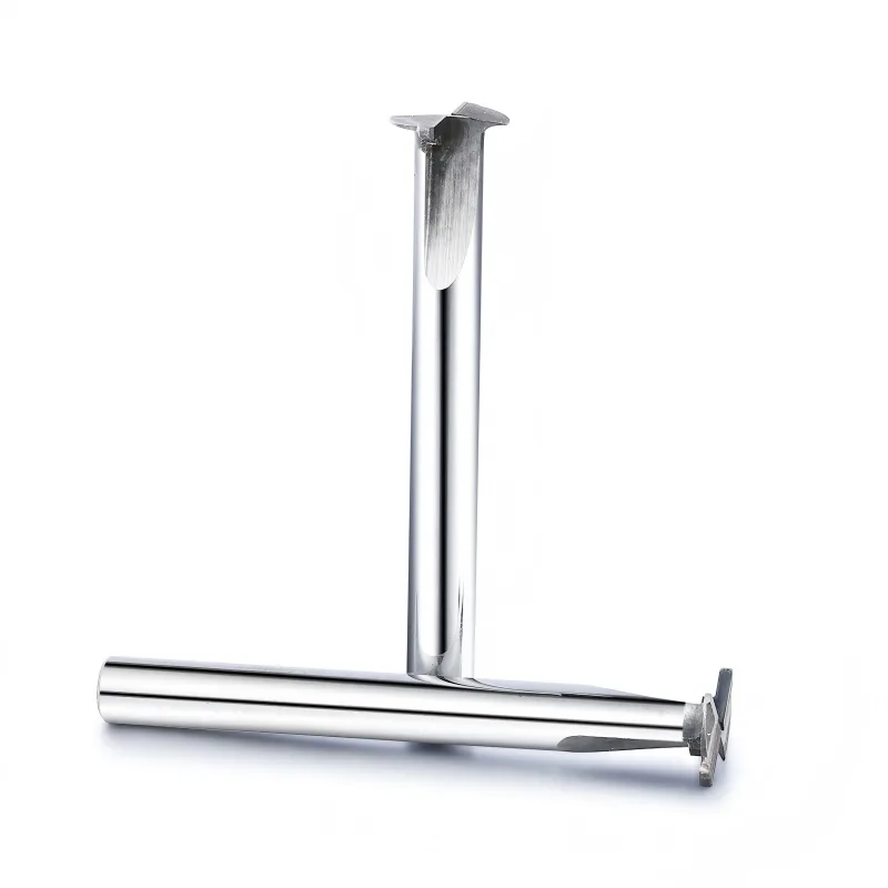
Angled grooves, retaining features and recessed dovetail profiles.
View tool range →PCD tools · Non-ferrous profiles and abrasive workpieces
Compare polycrystalline diamond tools for non-ferrous and abrasive workpieces, including dovetail, form, chamfer, slot and single-edge cutters.
PCD tooling is reviewed around workpiece composition, feature geometry and the expected production run. Start with a drawing for dovetails, internal grooves or combined profiles. The relationship between the cutting head, neck and entry opening can determine whether the tool is feasible.
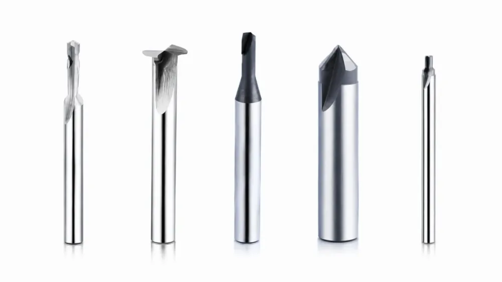
Explore the family
Compare the feature each tool solves, then open the relevant range for application and ordering details.
Angled grooves, retaining features and recessed dovetail profiles.
View tool range →Drawing-based stepped profiles and combined non-ferrous features.
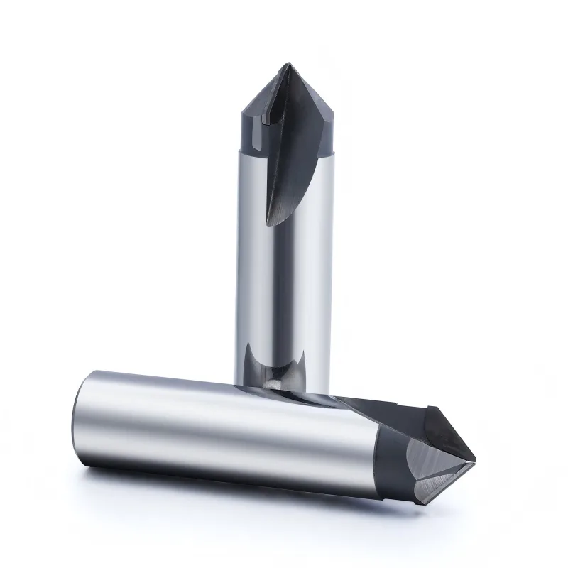
View tool range →Chamfered edges, countersinks and deburring on abrasive non-ferrous parts.
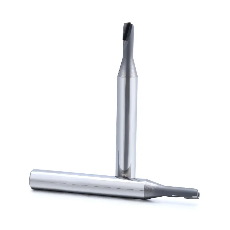
View tool range →Single-edge cutting for non-ferrous and non-metallic profiles.
View tool range →Application guide
Use the part feature and its acceptance requirements to narrow the tool choice.
Compare the required contour and dimensional relationship between connected features.
Check entry, cutting and withdrawal clearances in a section view.
Define chamfer or countersink dimensions and the acceptable edge condition.
Application & selection
Use the drawing and actual machining conditions to define a configuration for this tool family.
Provide the exact non-ferrous material or composite specification, including fillers or reinforcement where relevant. PCD selection depends on the application; a general material family name is not enough to transfer another tool recommendation.
Show the radii, angles and widths that must remain related in a form cut. Identify the datum from which they are inspected. This is especially useful when one tool replaces several separate profile operations.
For dovetails and undercuts, show how the head enters the feature and leaves it. Include the opening, neck clearance and neighboring walls. The finished groove dimensions alone do not prove the tool can reach it.
Describe burrs, breakout or surface requirements at the cut boundary. Mark the critical face and the inspection method. If later processing changes the edge, include that sequence in the application brief.
Application & selection
Use the drawing and actual machining conditions to define a configuration for this tool family.
Send the component drawing and the target cutting contour. Mark the feature to be produced and the allowed tool approach. A section view is more useful than a product name for recessed or combined profiles.
Include shank requirements, available holder dimensions and the usable machine envelope. Identify the cutting diameter and required neck clearance separately. Provide the current tool drawing if the new tool must fit an established setup.
State quantity, dimensional acceptance and the expected production operation. For a new profile, describe the sample evaluation and reporting needed. Use the agreed tool drawing as the reference for later orders.
Selection & configuration
PCD selection starts with the workpiece composition and cutting access. A custom profile can combine features, but chip clearance, cutting force and regrinding allowance need a drawing review.
| Decision | What to specify | Why it matters |
|---|---|---|
| Composition | Exact alloy or composite specification | A broad non-ferrous label is not enough to approve a cutting material. |
| Profile | Angles, radii and connected dimensions | These establish the form and inspection requirements. |
| Production | Batch size and present wear behavior | The case for PCD should be tied to the actual process. |
Swipe the table to compare all columns →
Include these details so the tool dimensions and application can be reviewed together.
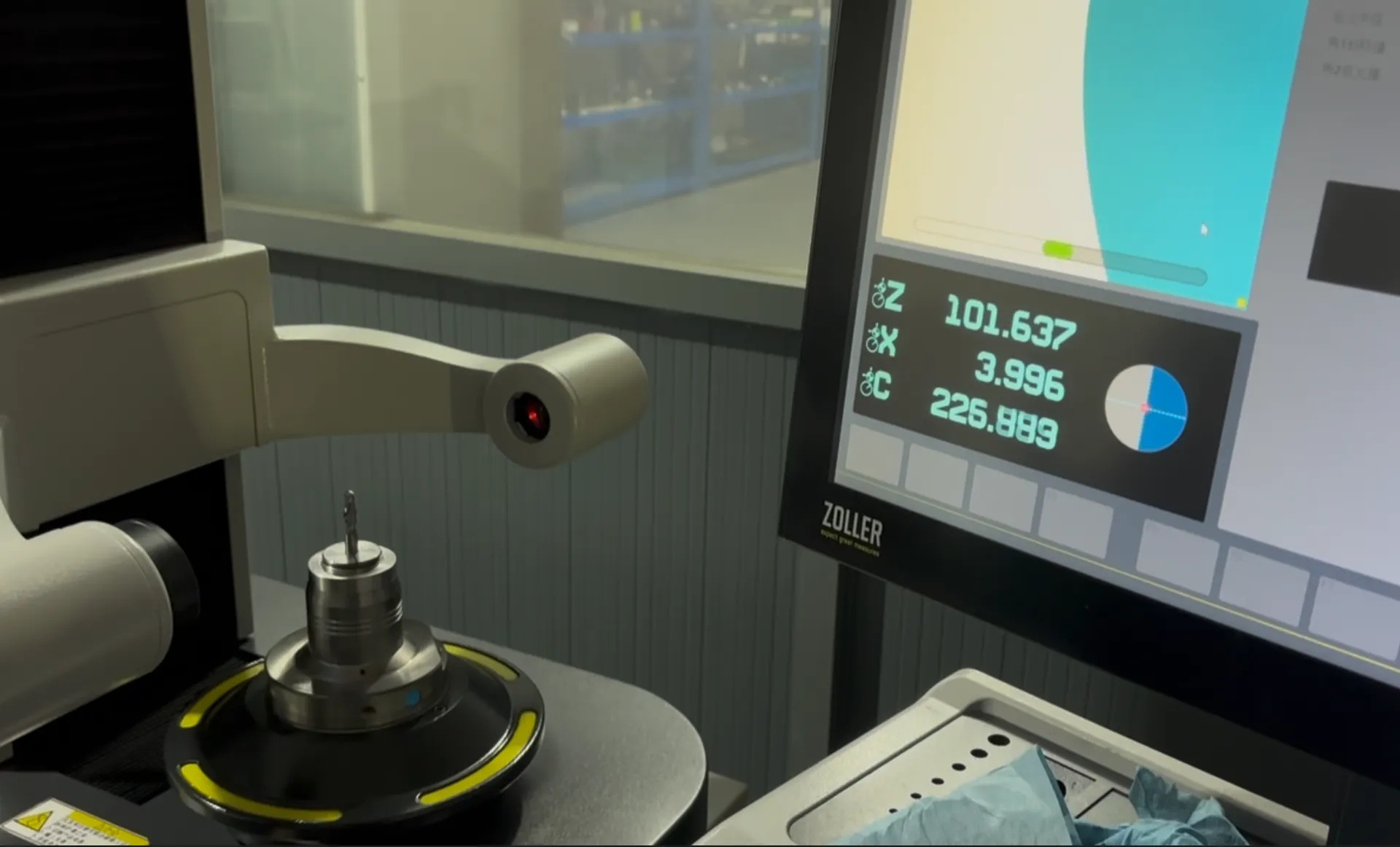
From drawing to inspection
A tool specification should describe both the cutting geometry and the acceptance requirements. Mark critical dimensions on the drawing and discuss how they will be checked before ordering.
Selection questions
Practical answers for pcd end mills & milling tools.
When a defined contour or several connected features can be machined by one profile. Check access, engaged cutting length and inspection before assuming the combined tool will improve the process.
Material composition; feature drawing; profile tolerance; edge-finish requirement; annual quantity. Add the quantity and delivery destination. A drawing or marked part section helps identify critical dimensions and clearance constraints.
The quotation and agreed drawing define the tool configuration, inspection scope, quantity and delivery schedule. Reference images show the tool family; use the confirmed specification for ordering.
Start with your application
Send your drawing or machining requirement. Your selected tool category and a checklist will be carried into the inquiry form.