Stepped profiles
Identify the relationship between cutting diameters and axial positions.
Combined profiles · Non-ferrous form machining
Drawing-based stepped profiles and combined non-ferrous features.
A PCD form cutter is developed around a defined contour or a set of connected features. Mark the critical dimensions and the surfaces that will engage simultaneously. This establishes the profile, access and inspection review before a tool drawing is finalized.
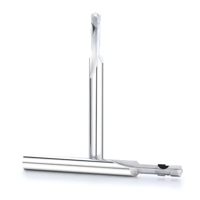
Application guide
Use the part feature and its acceptance requirements to narrow the tool choice.
Identify the relationship between cutting diameters and axial positions.
Show connected radii, shoulders and angles on one section.
State the dimensional drift that would trigger a tool change.
Selection & configuration
Identify critical dimensions and the intended inspection method. Combining features increases the engaged edge length and can change machine power and rigidity requirements.
| Decision | What to specify | Why it matters |
|---|---|---|
| Profile drawing | Datums, connected dimensions and tolerances | These establish what the tool must reproduce. |
| Material | Alloy or abrasive workpiece composition | The cutting material choice needs a specific application. |
| Engaged edge | Features cut at the same time | Combining a profile changes load and chip space. |
Swipe the table to compare all columns →
Include these details so the tool dimensions and application can be reviewed together.
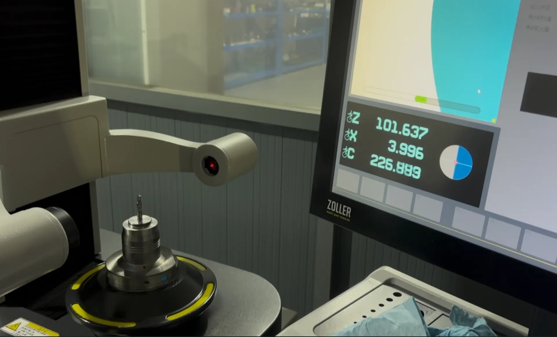
From drawing to inspection
A tool specification should describe both the cutting geometry and the acceptance requirements. Mark critical dimensions on the drawing and discuss how they will be checked before ordering.
Selection questions
Practical answers for custom pcd form milling cutters.
Yes, the component drawing is a suitable starting point for review. Include access, machining direction and the current operation sequence so the proposed tool can be assessed.
Workpiece composition; feature drawing; profile tolerance; cutting access; production quantity. Add the quantity and delivery destination. A drawing or marked part section helps identify critical dimensions and clearance constraints.
The quotation and agreed drawing define the tool configuration, inspection scope, quantity and delivery schedule. Reference images show the tool family; use the confirmed specification for ordering.
Start with your application
Send your drawing or machining requirement. Your selected tool category and a checklist will be carried into the inquiry form.