Full-depth outlines
Evaluate edge condition on the upper and lower faces.
Laminated materials · Top and bottom edge control
Opposed cutting directions for edge control in laminates.
A compression cutter combines opposing flute directions. The location of the transition relative to the material thickness is part of the tool selection. Define both-face edge requirements and the actual sheet thickness before choosing cutting length.
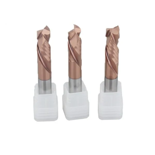
Application guide
Use the part feature and its acceptance requirements to narrow the tool choice.
Evaluate edge condition on the upper and lower faces.
Record the actual thickness and any surface layers.
Check support and chip or dust removal around the cut.
Selection & configuration
Position the flute transition inside the material thickness. A mismatch between transition height and sheet thickness can damage one face.
| Decision | What to specify | Why it matters |
|---|---|---|
| Sheet thickness | Actual thickness including face layers | The flute transition must be considered relative to both faces. |
| Transition position | Length of the lower cutting section | Its position changes how the two edges are engaged. |
| Edge acceptance | Fraying, delamination and finished size | Evaluate both faces rather than only the visible top edge. |
Swipe the table to compare all columns →
Include these details so the tool dimensions and application can be reviewed together.
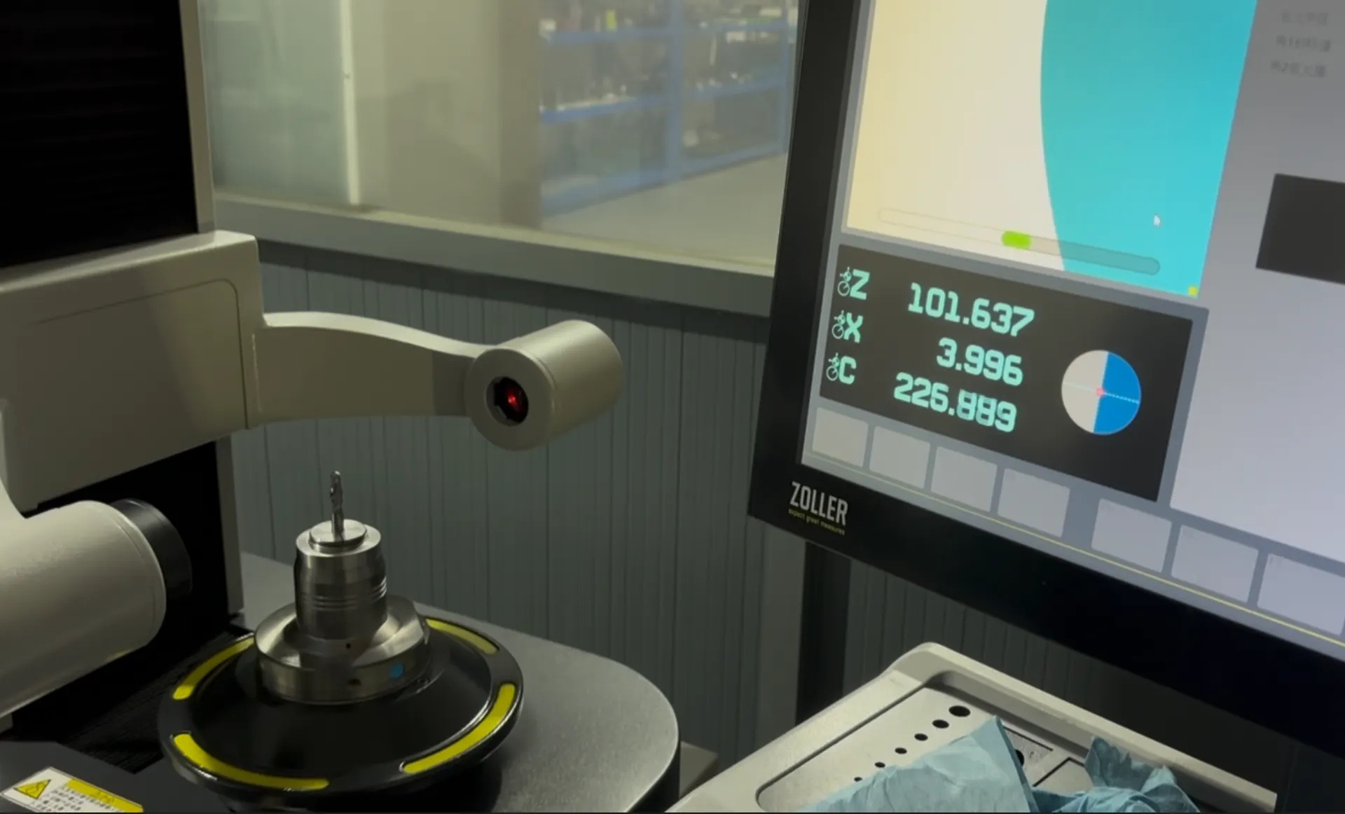
From drawing to inspection
A tool specification should describe both the cutting geometry and the acceptance requirements. Mark critical dimensions on the drawing and discuss how they will be checked before ordering.
Selection questions
Practical answers for compression end mills.
The upcut and downcut sections act at different positions along the tool. Their transition must be considered relative to the sheet so the intended cutting action reaches both edges.
Part drawing; workpiece material; cutting access; critical tolerance; current process; quantity. Add the quantity and delivery destination. A drawing or marked part section helps identify critical dimensions and clearance constraints.
The quotation and agreed drawing define the tool configuration, inspection scope, quantity and delivery schedule. Reference images show the tool family; use the confirmed specification for ordering.
Start with your application
Send your drawing or machining requirement. Your selected tool category and a checklist will be carried into the inquiry form.